Harmonic Measurement: What It Is and How to Do It

Harmonic measurement (Oberschwingungsmessung) records the non-sinusoidal current and voltage components that devices like variable-frequency drives feed back into your grid. It quantifies these distortions so you can judge power quality and act before heat, malfunctions, or wear appear.
Harmonics are voltage and current components at whole-number multiples of the 50 Hz mains frequency (150 Hz, 250 Hz, 350 Hz, and so on). A harmonic measurement captures the current and voltage waveform at a point in the installation and breaks it down into these individual orders. The result shows how far the real signal deviates from a clean sine wave — the core question behind any power-quality assessment.
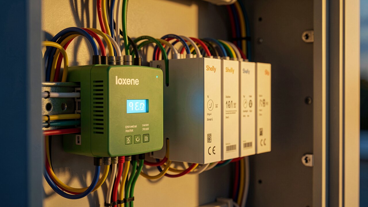
1) Connect a power-quality analyzer or network analyzer at the point of interest (e.g. the switchgear or the supply of a suspect load). 2) Record voltage and current over a representative period that includes normal operation. 3) The instrument performs a spectral analysis, splitting the signal into its harmonic orders. 4) Read out the per-order amplitudes and the summary distortion figures. 5) Compare against the values expected for a clean network to locate the source.
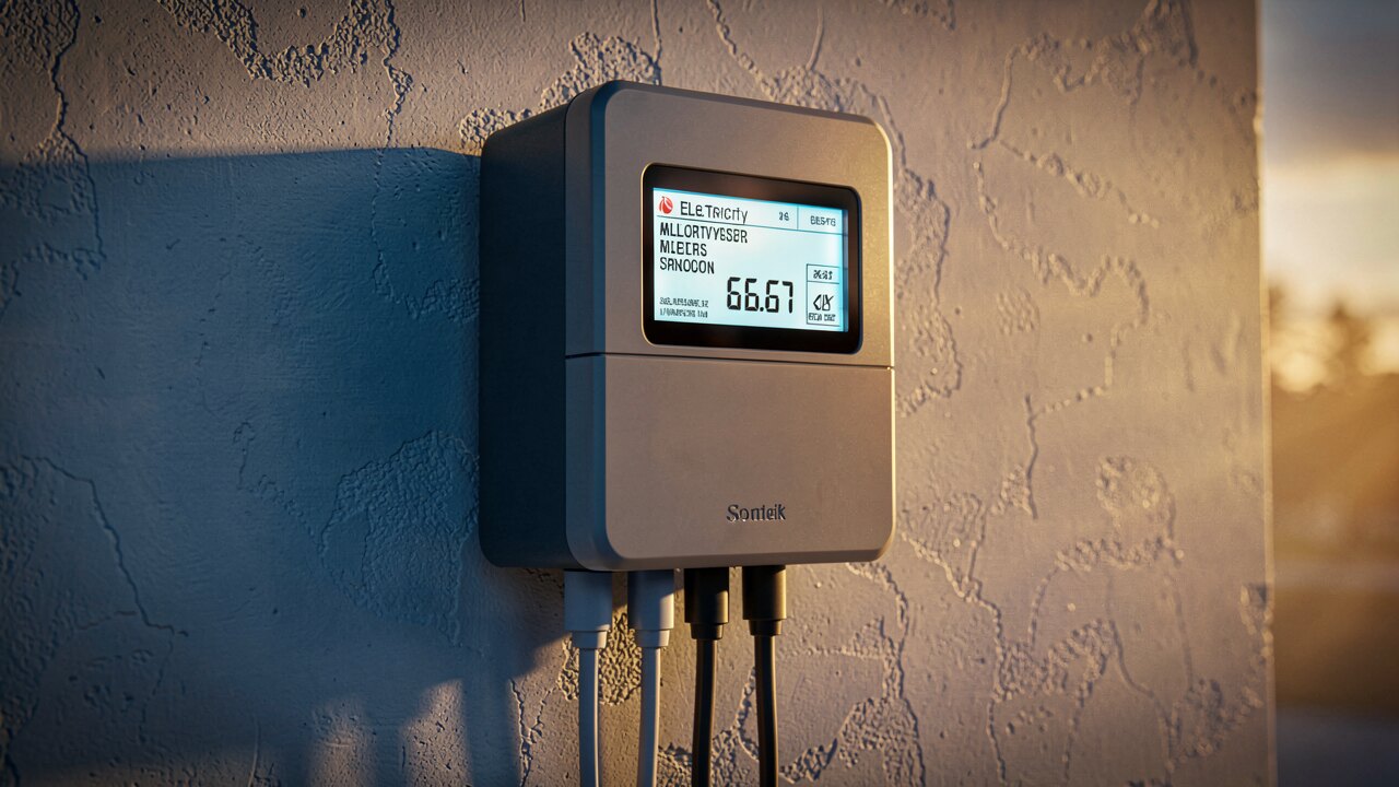
The key figures are THD (total harmonic distortion), stated separately for voltage (THD-U) and current (THD-I), plus the amplitude of each individual harmonic order. High current THD points to a distorting load such as a frequency converter; voltage THD shows how strongly that distortion already affects the shared network. The dominant orders (often the 5th and 7th with six-pulse drives) hint at the type of source.
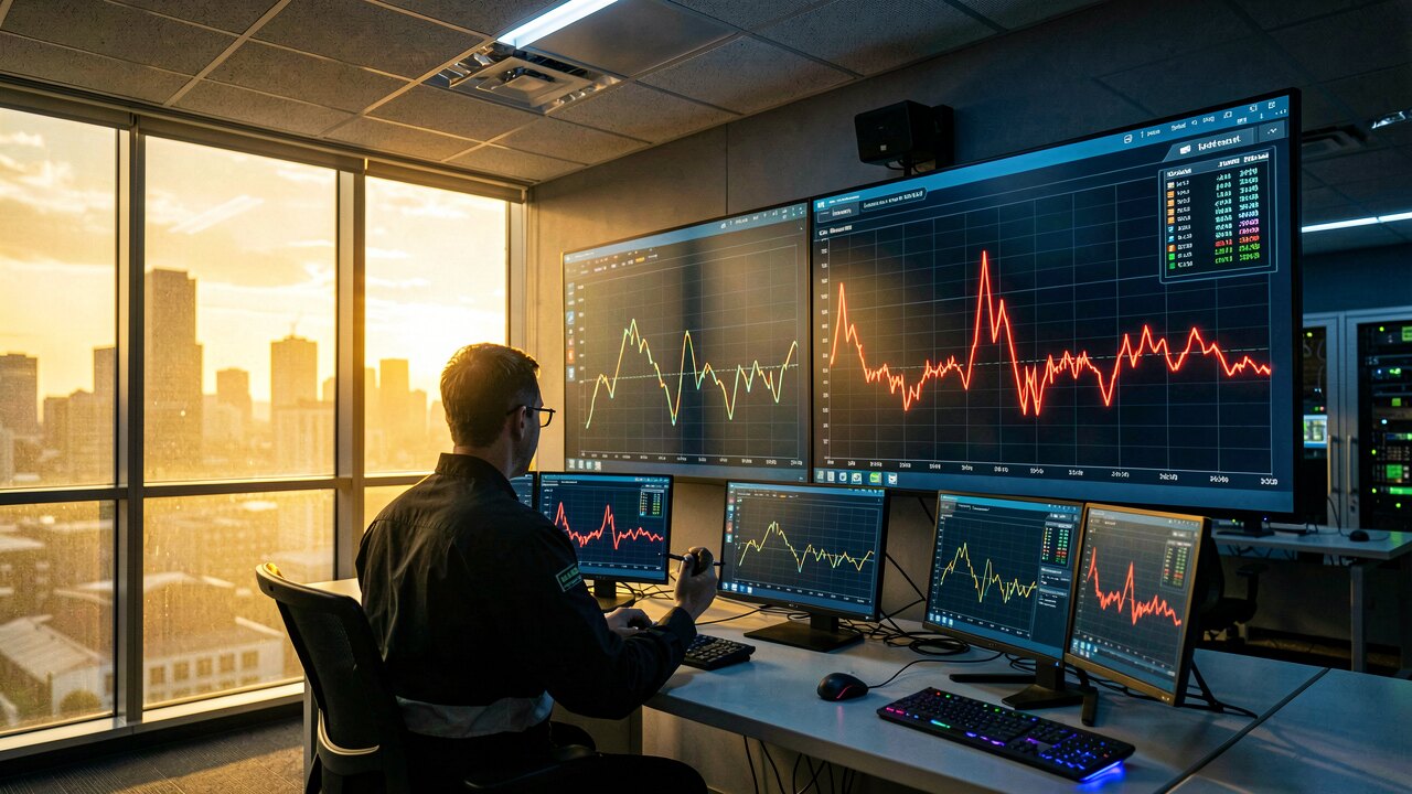
Measure directly at or close to the suspected source — for example the input of a variable-frequency drive — and, for comparison, at the point of common coupling where several loads meet. Measuring at a single point rarely tells the whole story: a live network analysis across the switchgear reveals both the emitting device and how far the distortion spreads through the installation.
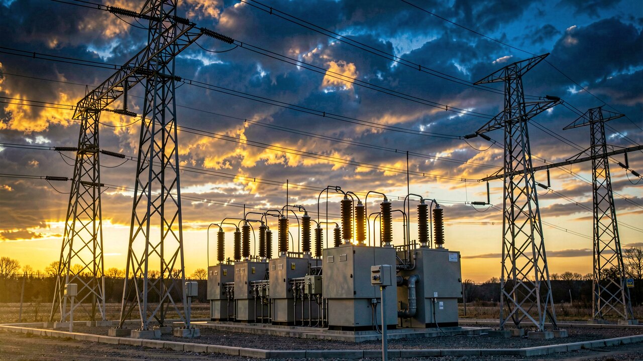
Typical emitters are frequency converters, which draw non-sinusoidal current every time they switch and push those harmonics back into the operating network. Other power-electronic loads and large inverter-based generators (for example big photovoltaic plants) also emit harmonics. A measurement helps separate one contributor from another rather than guessing from symptoms alone.
Uncontrolled harmonics cause additional heating in cables, transformers and motors, can trip protective devices, disturb electronics, and accelerate wear. A harmonic measurement turns these vague symptoms into concrete numbers, so any countermeasure — filtering, reactors, or reconfiguration — is chosen based on evidence instead of assumption.