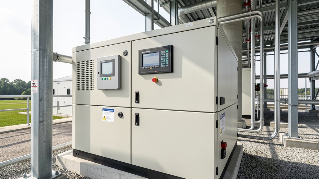
Harmonics: Sources and Characteristics in PV Systems
Harmonics are integer multiples of the fundamental frequency (50/60 Hz) generated by non-linear electrical loads. In PV systems, harmonics originate from inverter switching operations (PWM), rectifiers, and other non-linear devices. The Total Harmonic Distortion (THD) quantifies harmonic content as a percentage of the fundamental frequency. For example, a 5th harmonic at 250 Hz in a 50 Hz system contributes to voltage distortion.
Non-linear loads draw current in non-sinusoidal waveforms, causing harmonic currents that propagate through the grid. These harmonics can interact with system impedance, leading to voltage distortion at the Point of Common Coupling (PCC). Harmonic levels increase with higher inverter switching frequencies and poor filtering, potentially exceeding IEEE 519 limits.
Harmonic mitigation requires targeted solutions. Passive LC filters tuned to specific harmonics or active harmonic filters (AHF) that inject opposing currents. However, passive filters risk resonance with grid impedance, while AHF consume 1-3% of system capacity for operation. Proper system design is critical to avoid amplifying harmonics.
Flicker: Causes and Measurement Standards
Flicker refers to perceptible light fluctuations caused by rapid voltage changes. In PV systems, flicker occurs due to sudden power variations from cloud cover, inverter switching, or load changes. The short-term flicker severity (Pst) and long-term (Plt) are measured per IEC 61000-3-7, with Pst ≤1.0 typically required for public networks.
Voltage fluctuations are quantified by the rate and magnitude of changes. A 0.5% voltage change per second can cause noticeable flicker. Flickermeters simulate human perception, analyzing voltage deviation over time. High-frequency fluctuations (e.g., from rapid cloud transients) significantly increase Pst values.
Grid operators enforce Pst limits to prevent disruption. For example, industrial facilities may experience equipment malfunctions if Pst exceeds 1.0. Mitigation requires stabilizing voltage through reactive power control or energy storage to smooth power injections.
Impact on Grid and Equipment
Harmonics cause overheating in transformers and motors due to skin effect and eddy currents. Capacitors may fail from harmonic resonance, leading to increased losses and reduced lifespan. Voltage distortion can disrupt sensitive electronics, causing data errors or shutdowns in industrial control systems.
Flicker affects lighting systems and sensitive equipment. Rapid voltage changes can trigger false trips in relays, disrupt PLC operations, and cause visible flicker in LED lighting. In commercial settings, this may lead to productivity loss or safety issues in environments requiring stable power.
Combined effects of harmonics and flicker can degrade overall system reliability. For instance, harmonic-induced voltage distortion may exacerbate flicker severity, creating a compounding issue that requires integrated mitigation strategies.
Harmonic Distortion Standards (IEEE 519)
IEEE 519-2014 defines harmonic limits based on system voltage and short-circuit ratio (Isc/Iload). For low-voltage systems (≤1 kV), voltage THD must not exceed 5%, with individual harmonics limited to 3% for odd orders up to 11th. Higher-order harmonics have stricter limits (e.g., 1.5% for 13th-35th).
The standard requires measurement at the PCC. Compliance depends on the ratio of available short-circuit current to load current. For example, if Isc/Iload > 100, THD limit is 5%; if 50 < Isc/Iload ≤ 100, THD limit is 4%. This ensures harmonic limits scale with grid strength.
Non-compliance risks grid instability and equipment damage. Utilities may impose penalties or require corrective actions. Engineers must conduct harmonic studies during design to ensure adherence, considering existing harmonic sources and future expansions.
Flicker Standards and Metrics
IEC 61000-3-7 specifies flicker limits for public low-voltage networks. Short-term flicker severity (Pst) must remain ≤1.0 over 10 minutes, while long-term (Plt) ≤0.65 over 2 hours. These metrics are calculated using a flickermeter that models human sensitivity to voltage fluctuations.
Rapid power changes from PV systems, such as those caused by cloud cover, can exceed Pst thresholds. For example, a 5% voltage change within 1 second may result in Pst >1.0. Mitigation requires stabilizing voltage through reactive power injection or energy storage to dampen fluctuations.
Grid operators enforce these limits to maintain power quality. Exceeding Pst thresholds can lead to connection rejections or operational restrictions. Continuous monitoring and adaptive control are essential for compliance in dynamic PV environments.
Harmonic Mitigation Techniques
Passive harmonic filters use LC circuits tuned to specific frequencies (e.g., 5th, 7th harmonics). However, they risk resonance with grid impedance, potentially amplifying harmonics. Detuned filters with series reactors mitigate this by shifting resonance above harmonic frequencies.
Active harmonic filters (AHF) inject opposing currents to cancel harmonics in real-time. They offer flexibility but consume 1-3% of system capacity. Modern inverters with built-in harmonic cancellation can reduce THD to <3% when configured correctly, though this may reduce available active power.
Hybrid solutions combine passive and active filtering for cost-effectiveness. Critical applications may require dedicated AHF for high harmonic loads. System design must include impedance analysis to avoid resonance and ensure effective mitigation.
Reactive Power Compensation for Flicker Reduction
Reactive power (VAr) support stabilizes voltage by compensating for reactive load demands. In PV systems, inverters can inject or absorb VAr to maintain voltage within limits during rapid power changes. This reduces flicker caused by voltage fluctuations from cloud transients or load switching.
However, VAr injection reduces available active power. For example, injecting 20% of rated power as VAr lowers active power output by the same amount. IEEE 1547-2018 allows inverters to provide VAr support, but grid codes may restrict maximum VAr capacity based on system requirements.
Dynamic VAr control algorithms adjust reactive power in real-time based on voltage measurements. This requires precise monitoring and fast response times (e.g., <100 ms). Proper coordination with grid operators ensures compliance while maximizing system efficiency.
Real-Time Monitoring Systems
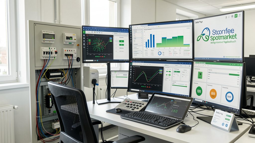
Power quality analyzers with IEC 61000-4-30 compliance measure THD, Pst, voltage, and current. Sampling rates ≥50 kHz are required for accurate flicker measurement. Data is logged and transmitted via SCADA for continuous oversight.
Monitoring must capture transient events and long-term trends. For example, a 10-minute Pst calculation requires high-resolution voltage data. Communication latency must be minimized to enable real-time corrective actions, such as adjusting inverter VAr output.
Edge cases include high background harmonics or rapid flicker events. Systems must differentiate between grid-induced and locally generated issues. Data logging supports compliance reporting and troubleshooting, ensuring proactive maintenance.
Implementation Steps and Constraints
Step 1: Conduct a power quality audit to identify harmonic and flicker sources. Measure THD and Pst at the PCC under various operating conditions. Step 2: Design mitigation solutions based on findings, considering passive filters, AHF, or VAr control.
Constraints include physical space for filters, cost of active systems, and grid operator requirements. For example, AHF installation may require additional cooling. System upgrades must comply with local regulations and avoid interference with existing equipment.
Step 3: Install and commission solutions with rigorous testing. Step 4: Implement continuous monitoring to verify compliance. Regular maintenance ensures filters remain effective, especially in environments with changing harmonic profiles.
Edge Cases and Special Scenarios
High harmonic background levels from industrial neighbors can overwhelm local mitigation. Solutions require coordinated grid-wide strategies, such as dedicated filters or utility-side interventions. In such cases, standalone systems may not suffice without grid operator cooperation.
Rapid flicker events from multiple PV systems switching simultaneously can exceed Pst limits. Mitigation involves distributed control algorithms that coordinate inverters to smooth power injections. Energy storage systems can absorb excess power during cloud transients, reducing voltage fluctuations.
Grid code variations by region complicate compliance. For example, German grid codes (VDE-AR-N 4105) have specific requirements for harmonic limits and flicker. Systems must be designed to meet the strictest applicable standards for operational flexibility.
FAQ
Can reactive power compensation reduce harmonics?
No. Reactive power compensation (VAr injection) corrects power factor but does not mitigate harmonic distortion. Harmonics require dedicated solutions such as passive filters, active harmonic filters, or inverter-specific harmonic cancellation features.
What are typical THD limits for commercial PV systems?
IEEE 519-2014 mandates voltage THD ≤5% at the PCC for low-voltage systems. Individual harmonic limits apply (e.g., 3% for 5th harmonic). Compliance depends on the short-circuit ratio (Isc/Iload), with stricter limits for weaker grids.
How does flicker affect industrial equipment?
Flicker can cause PLC malfunctions, motor speed variations, and lighting issues. Equipment may trip or malfunction if Pst exceeds 1.0, leading to production downtime or safety hazards in sensitive environments.
What monitoring tools are used for harmonics and flicker?
IEC 61000-4-30 compliant power quality analyzers with ≥50 kHz sampling rates. Real-time data is transmitted via SCADA for continuous oversight, enabling immediate corrective actions and compliance reporting.
Can battery storage help with flicker mitigation?
Yes. Battery systems absorb or inject active/reactive power during rapid fluctuations (e.g., cloud transients), stabilizing voltage and reducing Pst. This requires coordination with inverters and grid operator approval.
What’s the role of PV inverters in harmonic mitigation?
Modern inverters can include active harmonic filtering, reducing THD to <3%. They may also provide VAr support for voltage stability. However, harmonic mitigation capabilities depend on inverter design and configuration.
How do you handle resonance issues with passive filters?
Detuned filters with series reactors shift resonance frequencies above harmonic orders. System impedance analysis is critical before installation to avoid amplifying harmonics. Regular monitoring ensures filter performance remains optimal.
Are there specific grid codes for harmonics in PV systems?
Yes. Grid codes like EN 50160 and VDE-AR-N 4105 specify harmonic limits. Requirements vary by region but generally align with IEEE 519 or IEC standards. Compliance is mandatory for grid connection.