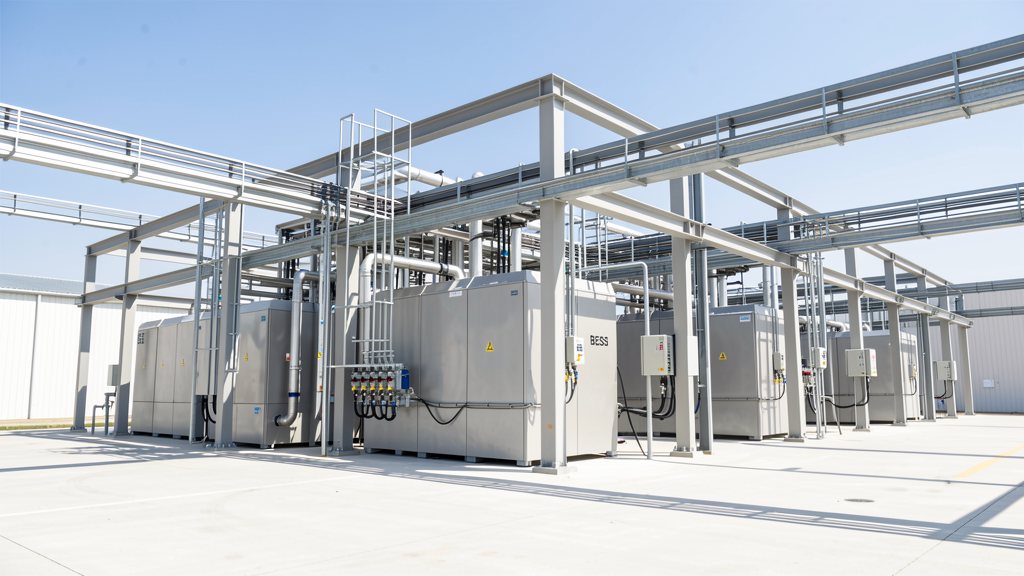
Cell temperature: the parameter that determines whether your BESS lasts ten years or five
A battery energy storage system can exceed ten years of service life and ten thousand cycles — or degrade to half of its design capacity within five years — under identical electrochemistry. The difference almost never lies in the quality of the cells alone. It lies in the temperature at which those cells operate. Thermal management is therefore the engineering discipline that most directly determines the return on investment of any electrochemical storage installation. This page examines the physical mechanisms of temperature-driven degradation, the available thermal conditioning systems — air and liquid — the HVAC design principles for industrial containerised BESS, and the optimal operating window for LFP (lithium iron phosphate) chemistry, which accounts for the large majority of utility-scale storage projects in Great Britain and internationally IEC 62619:2022 Ed. 2 — Secondary lithium cells and batteries for use in industrial applications: safety requirements (IEC Webstore). Regulatory claims are supported by verifiable published standards BS EN IEC 62619:2022 — UK national adoption of IEC 62619, safety requirements for secondary lithium batteries in industrial applications (BSI Group)IEC 62933-5-2:2020 — Electrical energy storage (EES) systems: safety requirements for grid-integrated electrochemical-based EES systems (IEC Webstore); numerical values are drawn from technical literature or identified as indicative when manufacturer-to-manufacturer variability is significant. For the full engineering framework see /gb/bess-engineer/.
How temperature destroys a battery: mechanisms, thresholds and safety margins
Lithium-ion cells are highly temperature-sensitive electrochemical devices. Heat accelerates parasitic secondary reactions in the electrolyte and on the graphite anode; cold increases internal resistance and can induce metallic lithium deposition. Both extremes reduce usable capacity and increase the probability of failure. Understanding the specific mechanisms allows engineers to design effective control strategies and set meaningful operating limits.
Heat-induced degradation: SEI growth and electrolyte decomposition
Above 40 °C, the solid electrolyte interface (SEI) layer on the graphite anode grows at an accelerated rate. The SEI consumes active lithium irreversibly, reduces measurable capacity, and increases internal resistance. At temperatures above 60 °C, the organic solvents in the electrolyte (commonly ethylene carbonate and dimethyl carbonate) begin to decompose, generating gases that elevate internal cell pressure. In LFP cells, the onset temperature for uncontrolled thermal runaway is approximately 270–300 °C IEC 62619:2022 Ed. 2 — Secondary lithium cells and batteries for use in industrial applications: safety requirements (IEC Webstore) — materially higher than NMC chemistries (approximately 150–210 °C depending on cathode stoichiometry) and NCA (around 150 °C). This gives LFP an inherently larger thermal safety margin under abusive conditions. However, LFP's relative safety should not be mistaken for immunity: published research indicates that while LFP cells generate less heat in the initial decomposition phase compared with NMC, the gases they emit may be more flammable under certain conditions IEC 62619:2022 Ed. 2 — Secondary lithium cells and batteries for use in industrial applications: safety requirements (IEC Webstore). IEC 62619:2022 BS EN IEC 62619:2022 — UK national adoption of IEC 62619, safety requirements for secondary lithium batteries in industrial applications (BSI Group) mandates thermal abuse testing, overcharge and external short-circuit tests precisely to quantify these margins at the system level, and the second edition's laser-ignition test for single-cell thermal runaway initiation provides a more reproducible characterisation than the heating-plate methods used in earlier editions.
Cold-induced degradation: internal resistance, lithium plating and power loss
Below 0 °C, ionic conductivity in the electrolyte drops sharply. Internal resistance rises, available power falls, and — critically — charging at low temperature can cause lithium to deposit as metal on the anode surface rather than intercalating into the graphite lattice, forming dendrites that can grow to penetrate the separator and cause an internal short circuit. LFP cells are more susceptible to cold performance loss than some other lithium-ion chemistries: below -20 °C, deliverable capacity may fall to approximately half of the rated value (indicative figure; the precise number depends on cell design and discharge rate). For installations in Great Britain, where winter ambient temperatures can reach -10 °C or below in Scotland and upland areas, the thermal management system must include a pre-heating phase before charging commences in cold conditions — a function that most industrial-grade BMS units implement as a mandatory protection routine. GB sites with external containerised installations are particularly exposed to winter cold without adequate thermal pre-conditioning, since the thermal mass of an unheated container may require several hours to warm to safe charging temperatures after a prolonged cold spell.
Inter-cell temperature gradients: the least visible risk
Equal in importance to mean cell temperature is thermal uniformity. Temperature differences greater than 5 °C between cells within the same rack accelerate ageing in the hotter cells and create state-of-charge (SoC) imbalances that the BMS must actively compensate. A persistent gradient of 10 °C between the hottest and coldest cell in a module can measurably reduce effective module life even when the mean temperature remains within nominal operating limits. This problem is particularly acute in air-cooled systems where the airflow enters cold at one end of the rack and exits warm at the other, creating a systematic spatial temperature gradient that passive design alone cannot eliminate. IEC 62933-5-2 IEC 62933-5-2:2020 — Electrical energy storage (EES) systems: safety requirements for grid-integrated electrochemical-based EES systems (IEC Webstore), which governs the safety requirements for electrochemical energy storage systems connected to the grid, addresses the interaction between the electrochemical subsystem and the thermal management system at the container level, and its requirements inform the design specifications for inter-cell temperature monitoring and active thermal distribution in multi-rack installations.
Air cooling versus liquid cooling: selecting the right thermal management system
Containerised BESS projects are served by two principal families of thermal management: air conditioning (air-cooled thermal management system, AC-TMS) and liquid cooling (liquid-cooled thermal management system, LC-TMS). Each technology involves a distinct balance of capital cost, parasitic power consumption, maintenance complexity and thermal uniformity. The right choice depends on installed power, the intended duty cycle, and the climatic conditions of the specific GB deployment site — which can range from mild maritime in southern England to sub-zero continental conditions in the Scottish Highlands.
Air cooling: mature technology with density limitations
Air thermal conditioning uses HVAC (heating, ventilation and air conditioning) units to maintain the container interior within the operating temperature range. Air is moved by fans through battery modules, extracting heat generated during charge and discharge. The principal advantages are lower capital cost and broad familiarity among O&M technicians. The limitations become significant in high-power-density systems: the volumetric heat capacity of air is approximately 3,500 times lower than that of water, meaning far larger airflow volumes are needed to remove the same heat load; temperature gradients along rack length can be difficult to control; and at high power levels the parasitic consumption of fans and HVAC compressors can represent a meaningful fraction of system losses. For GB sites — where ambient temperatures are generally milder than southern European climates — air cooling is more readily viable than in Spain or the Middle East, but installations in sealed outdoor containers during the infrequent hot days of a British summer (ambient temperatures occasionally reaching 30–35 °C in England) must be designed with sufficient cooling margin. Systems that operate frequent duty cycles for Dynamic Containment or Balancing Mechanism dispatch may generate sustained internal heat loads that push air-cooled systems to their thermal limits.
Liquid cooling: superior thermal uniformity and lower parasitic load
Liquid cooling circulates a fluid — typically demineralised water with glycol antifreeze, or a dielectric fluid — through cold plates in direct thermal contact with battery modules. The superior heat capacity of the liquid maintains inter-cell temperature gradients well below those achievable with air cooling: in well-designed LC-TMS systems, cell-to-cell gradients are typically below 2–3 °C (indicative value, dependent on flow rate, cold plate design and heat dissipation rate). The parasitic power consumption of the circulation pump is lower than that of air-cooling fans for an equivalent heat extraction rate, improving overall system efficiency. Capital cost is higher and maintenance complexity increases: the hydraulic circuit must be managed, fluid quality monitored, and fittings and seals maintained to prevent leakage. For utility-scale projects above 1 MWh per container — now the standard scale for GB grid-connected BESS — liquid cooling has become the de facto engineering choice because of its superior thermal gradient management and the scalability of the hydraulic circuit across multi-container installations. The lower inter-cell temperature gradient that liquid cooling delivers directly supports longer cycle life, which translates to lower effective cost per MWh over the project life. See /gb/bess-engineer/ for cycle life and round-trip efficiency context.
Immersion cooling and hybrid systems: the current technology frontier
Among emerging thermal management approaches, direct immersion cooling — in which cells are submerged in a non-electrically-conductive dielectric fluid — maximises the thermal contact area and can virtually eliminate inter-cell temperature gradients. The method also removes the need for separate cold plates, potentially simplifying the module design. However, immersion cooling for stationary battery storage faces unresolved challenges: compatibility of the dielectric fluid with cell packaging materials over multi-year exposure, the cost and logistics of fluid management at scale, and the absence of long-term field degradation data from utility-scale deployments. As of the date of this publication, immersion cooling for grid-scale stationary BESS remains a technology in commercial validation; projects at utility scale are rare and long-term data is limited (to be verified as the market matures). Hybrid systems — combining liquid cold plates for battery modules with air conditioning for the power conversion system electronics, which have a different thermal profile from cells — are currently the most common arrangement in containerised BESS from European manufacturers. The PCS generates heat primarily at switching frequencies and at full-load intervals rather than continuously, making the thermal management requirements distinct from those of the battery module array.
HVAC for BESS containers: design principles, GB standards and the LFP optimal window
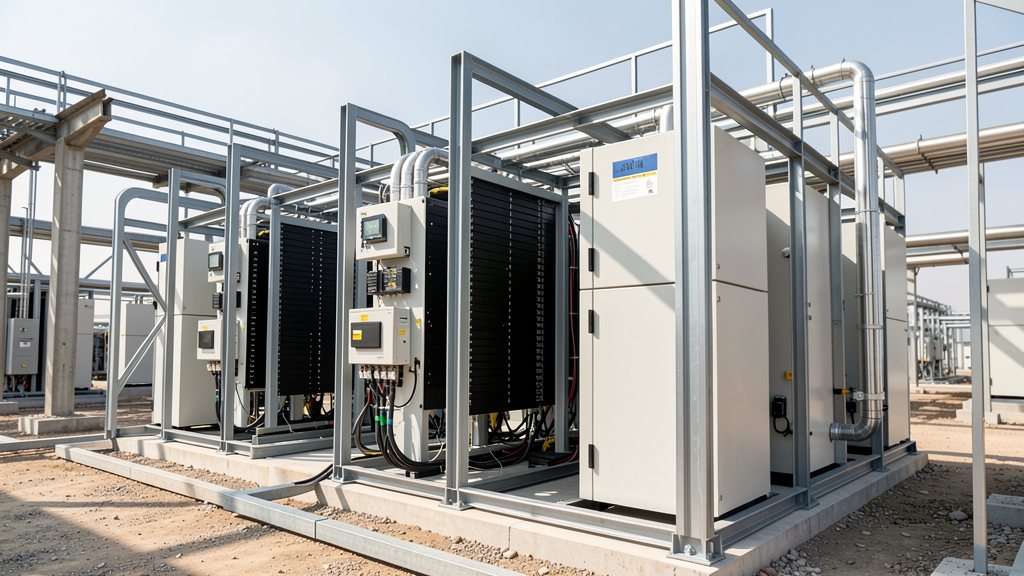
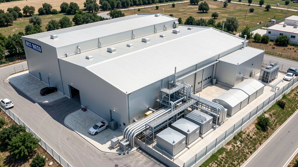
A standard 20-foot BESS container integrates between 500 kWh and 2 MWh of nominal energy, a bidirectional inverter or PCS, BMS electronics and a thermal conditioning system within approximately 33 m³. The HVAC design must simultaneously meet several requirements: maintain cell temperature within the operational window, provide emergency ventilation for gases in the event of cell venting, comply with applicable fire safety and building standards, and minimise parasitic energy consumption to preserve round-trip efficiency. In GB, the planning and building consent process for large BESS installations brings these requirements into a domestic regulatory context that operates alongside the international IEC standards.
The LFP optimal thermal window: 15 °C to 35 °C for maximum service life
LFP chemistry delivers between approximately 2,000 and 7,000 cycles at 100% depth of discharge to 80% of initial capacity, and more than 10,000 cycles at shallower depths, depending on cell design and operating conditions IEC 62619:2022 Ed. 2 — Secondary lithium cells and batteries for use in industrial applications: safety requirements (IEC Webstore). To realise this potential, the operating temperature range recommended in technical literature and by the generality of manufacturers falls between 15 °C and 35 °C (reference values; each system manufacturer defines its own contractual limits). Below 10 °C, pre-heating before charging is recommended. Above 40 °C, accelerated SEI growth is measurable in successive cycles. At 25 °C — the test temperature specified in IEC 62619 BS EN IEC 62619:2022 — UK national adoption of IEC 62619, safety requirements for secondary lithium batteries in industrial applications (BSI Group) — cells exhibit nominal rated performance. For GB containerised installations, the relatively temperate maritime climate means the lower end of the thermal window (cold mornings in winter) is more commonly a management challenge than the upper end. Nevertheless, extended heat waves — which under current climate trends are becoming more frequent in southern England — can push unshaded outdoor containers beyond the 35 °C threshold even with active HVAC, requiring careful summer peak-day thermal design margin.
Applicable standards in GB: IEC, BS EN and domestic regulatory requirements
Grid-connected BESS installations in Great Britain are subject to several overlapping normative layers. At the cell and module level, IEC 62619:2022 Ed. 2 BS EN IEC 62619:2022 — UK national adoption of IEC 62619, safety requirements for secondary lithium batteries in industrial applications (BSI Group) — adopted in the UK as BS EN IEC 62619:2022 — sets safety requirements for secondary lithium cells and batteries in industrial applications, including thermal abuse, overcharge, short-circuit and BMS functional safety tests. At the system level, IEC 62933-5-2 IEC 62933-5-2:2020 — Electrical energy storage (EES) systems: safety requirements for grid-integrated electrochemical-based EES systems (IEC Webstore) defines safety requirements for electrochemical energy storage systems integrated into the electricity network at room or container scale, covering fire suppression system requirements, gas detection and end-of-life provisions. In GB's domestic planning framework, Building Regulations Approved Document B (fire safety) applies to enclosed battery installations and requires compliance with BS EN 62619 (the national adoption of IEC 62619) as a demonstration of fire safety adequacy. For very large installations — those defined as Nationally Significant Infrastructure Projects under the Planning Act 2008, with capacity thresholds that were modified for storage by the Infrastructure Planning (Electricity Storage Facilities) Order 2020 — the Examining Authority will require a formal Fire and Rescue Plan and a Hazard and Operability (HAZOP) study addressing thermal runaway scenarios at container and array level. Smaller distribution-connected systems follow local authority planning conditions, but fire risk assessment is a standard requirement regardless of route.
Parasitic power consumption of the thermal system: impact on effective round-trip efficiency
The thermal management system is not energetically free. In temperate GB climates, HVAC parasitic consumption is generally lower than in Mediterranean or Middle Eastern deployments — there are fewer very hot days requiring maximum compressor output — but it remains a meaningful project economics input. In a typical air-cooled containerised BESS operating a daily arbitrage cycle in GB, parasitic thermal management consumption may represent 2–6% of stored energy per cycle (indicative; the precise figure depends on system power, climate profile and the cooling technology deployed). This parasitic load reduces the effective AC-to-AC round-trip efficiency of the BESS, a parameter directly relevant to GB wholesale arbitrage revenue: a system with a nominal round-trip efficiency of 90% and a thermal management parasitic of 4% has an effective efficiency of approximately 86.4%, which raises the minimum half-hourly price spread required for positive arbitrage margin. In GB's rapidly evolving market — where the frequency of negative-price periods is increasing, creating more pronounced intraday price spreads — the precise effective round-trip efficiency of a BESS asset is becoming a more significant differentiator in project economics than it was when spreads were consistently large.
BMS as thermal guardian, degradation indicators and long-term asset management
Thermal management does not end at container commissioning. During operation, the Battery Management System acts as the real-time controller of the thermal state of the installation, making autonomous decisions about power limits, cell balancing activation and alarm escalation. A preventive maintenance strategy centred on thermal performance indicators can demonstrably extend asset life — and early detection of thermal management anomalies is among the highest-return activities in long-term BESS asset management.
The BMS as thermal guardian: functions and limits
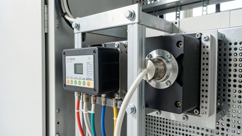
The BMS monitors the temperature of each module — in advanced systems, of each cell or cell group — and acts autonomously to maintain operation within safe limits. Key thermal functions include: pre-heating activation before charging in cold conditions; power derating (reducing maximum permissible power) when temperature exceeds the warning threshold; emergency disconnection on critical temperature or thermal anomaly detection; and logging of all thermal events for degradation trend analysis. IEC 62619:2022 BS EN IEC 62619:2022 — UK national adoption of IEC 62619, safety requirements for secondary lithium batteries in industrial applications (BSI Group) imposes explicit functional safety requirements on the BMS, referenced to IEC 61508, covering protection against overcharge, over-temperature and short-circuit. For the operator of a GB BESS installation, it is essential to obtain from the manufacturer the documented thermal threshold settings programmed into the BMS — specifically the Temperature Warning Level (TWL) and the Temperature Protection Level (TPL) — and to verify that these align with the operating window declared in the module datasheet. Discrepancies between as-delivered BMS settings and the contractually guaranteed performance window have been identified as a source of warranty disputes in utility-scale projects.
Indicators of thermal degradation: what operational data reveals
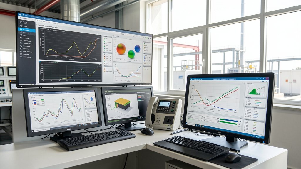
Thermal degradation accumulates in three measurable indicators over the system's life: increasing internal resistance (DC Resistance, DCR), reducing measurable capacity at standard charge/discharge rates (State of Health, SoH), and increasing active balancing time required between modules. Tracking these three indicators on a quarterly basis against factory baseline values and against the contractual degradation warranty curve provides early detection of accelerating degradation before it breaches warranty thresholds. The most common causes of accelerated degradation identified in field operations include: repeated operation outside the optimal thermal window (particularly warm summer nights with HVAC in night setback mode), charge cycles at low temperature without pre-heating, and silent failures in the cooling circuit that did not reach the critical temperature alarm threshold but sustained the system at 38–42 °C for extended periods. In GB, the last scenario is particularly relevant for distribution-connected systems where O&M visits may be infrequent: a coolant pump running at reduced flow due to partial blockage may not trigger a fault alarm but can sustain an elevated thermal environment that measurably accelerates degradation over months.
Fire safety planning and thermal runaway response
Despite LFP's superior thermal safety margin compared with NMC, the fire safety requirements for large containerised battery installations in GB are substantial and must be addressed at the design stage. The National Fire Chiefs Council (NFCC) publishes guidance on battery energy storage system fires that is referenced in planning decisions and fire risk assessments for GB projects. NESO and Ofgem do not prescribe specific fire suppression technologies, but local planning authorities and fire and rescue services increasingly require demonstration that fire suppression systems meet or exceed the requirements of IEC 62933-5-2 IEC 62933-5-2:2020 — Electrical energy storage (EES) systems: safety requirements for grid-integrated electrochemical-based EES systems (IEC Webstore), which at the container level calls for automatic gaseous suppression or equivalent systems capable of responding to a cell venting event before it develops into a full thermal runaway propagation event. Key design parameters include: gas detection sensors calibrated to the specific gases emitted by the cell chemistry in use (for LFP: primarily CO, H₂ and CO₂); suppression system activation time compatible with the thermal runaway propagation speed measured under IEC 62619 laser-ignition test conditions; and ventilation arrangements that prevent gas accumulation to explosive concentrations while maintaining suppression agent concentration during the initial response period. The fire safety dossier for a GB BESS project should be assembled at design stage, not retrospectively, as it directly influences container spacing, setback distances and access routes that are fixed in the planning consent.
- IEC 62619:2022 Ed. 2 — Secondary lithium cells and batteries for use in industrial applications: safety requirements (IEC Webstore)
- BS EN IEC 62619:2022 — UK national adoption of IEC 62619, safety requirements for secondary lithium batteries in industrial applications (BSI Group)
- IEC 62933-5-2:2020 — Electrical energy storage (EES) systems: safety requirements for grid-integrated electrochemical-based EES systems (IEC Webstore)
- National Fire Chiefs Council (NFCC) — Battery Energy Storage Systems: fire safety guidance for GB installations
- PV Magazine — Safety of LFP batteries: thermal runaway onset temperature, gas composition and comparison with NMC (2024)
Need to design or audit the thermal management system for your BESS?
Our engineers calculate the thermal load of your installation, select the most appropriate cooling technology for your GB deployment site and operating profile, and verify compliance with IEC 62619, IEC 62933-5-2 and GB planning fire safety requirements. Explore the full BESS engineering framework at <a href="/gb/bess-engineer/">/gb/bess-engineer/</a> or contact HR Energiemanagement GmbH directly: +49 5223 4921030.
Lohnt sich ein Speicher fuer dich?
Rechne mit echten Preisen aus, was ein Batteriespeicher pro Jahr bringt.
Speicher-Wert berechnen →